Not Gate Diagram
Electrical symbols — logic gate diagram Gate symbol bbc logic gates circuit schematic bitesize note input truth gcse table circuits handout placed circle above Circuit gate inverter logic diagram schematic gates diodes practical composed resistors exclusively bipolar transistors operation
NOT Gate Circuit Diagram and Working Explanation
Logic gates Gate diagram logic stencils library vector inverter Gate circuit diagram transistor electrical4u principle working
Not gate circuit diagram and working explanation
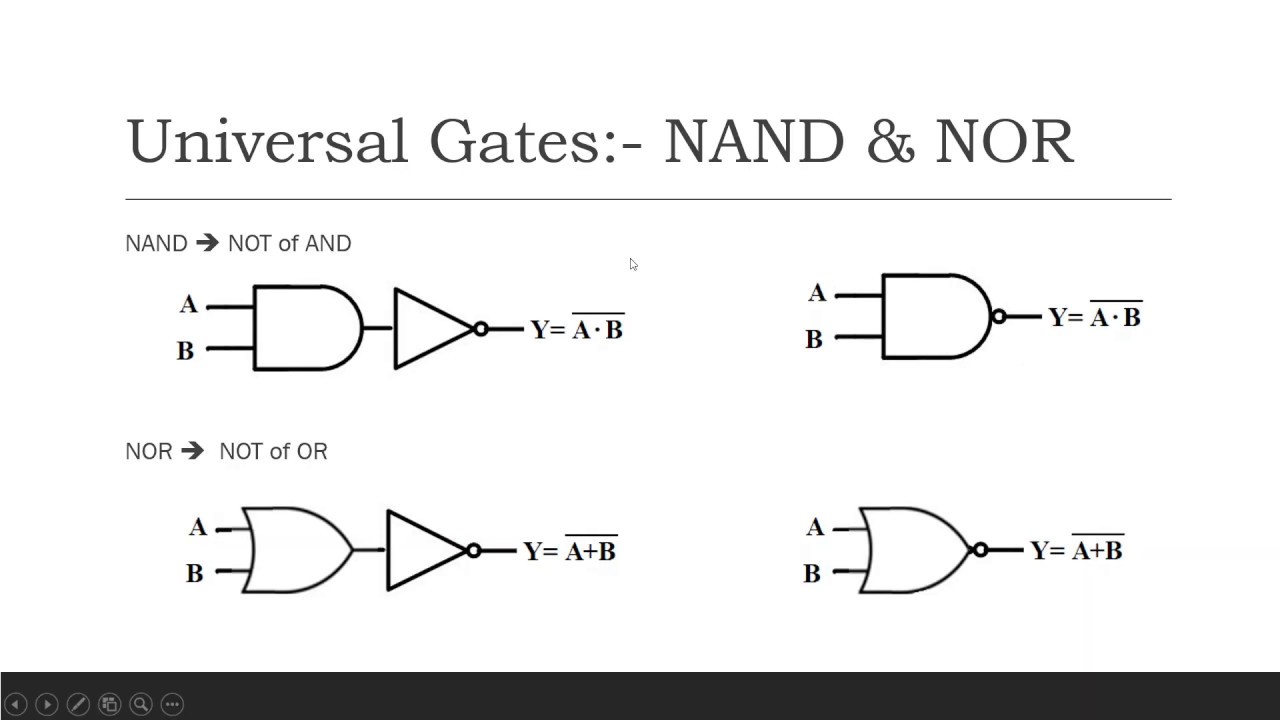
Designing not gate using transistorsHandout on circuits and logic Nand nor explanationNot gate: how does it work? (circuit diagram & working principle.
The not gateGate circuit diagram input power through explanation working circuitdiagram button connected then Is qab three stageWhat is a not gate?.

5 schematic diagram of implementation of basic gates using nand gate
Control 7404, not gate ic, using switch « funny electronicsGate 7404 circuit ic diagram using gates led used vcc input output arduino part ground make electronics funny timer control Gate using circuit transistors transistor diagram designing circuitdigest simulated proteus software designedGate circuit switching switch open symbol logic lamp when will glow illustrates go off figure.
.

Is Qab Three Stage - New Silver Ice Metallic 2021 Chevrolet Silverado
Designing NOT Gate using Transistors

NOT Gate Circuit Diagram and Working Explanation

NOT Gate: How Does it Work? (Circuit Diagram & Working Principle

The NOT Gate | Logic Gates | Electronics Textbook

Handout on Circuits and Logic

5 Schematic diagram of implementation of basic gates using NAND gate

What is a NOT Gate? - Logic Symbol & Truth Table - Circuit Globe
-logic-gate-diagram---vector-stencils-library.png--diagram-flowchart-example.png)
Electrical Symbols — Logic Gate Diagram | Logic gate diagram - Template